Before getting into the advanced analysis of wireless networks, Chapter 1 serves as a refresher of concepts covered in the CWNA (Certified Wireless Network Administrator) course, which is a prerequisite for the CWAP certification. If you’re reading this, it’s likely you already have a solid grasp of Wi-Fi basics and have completed your CWNA certification—or at least have a good understanding of the foundational material. This chapter revisits key concepts of wireless networking, such as the OSI model and 802.11 standards, setting the stage for more in-depth discussions on packet analysis, troubleshooting, and optimization.
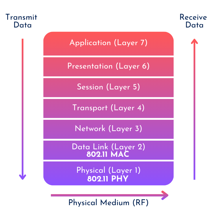
When diving into wireless networking, a solid understanding of the OSI Model is essential. This model breaks communication down into seven layers, each responsible for a different part of the data transmission process. In Wi-Fi, we primarily focus on Layer 1 (Physical) and Layer 2 (Data Link), where the core functions of transmission and management take place. Understanding these two layers is key to mastering wireless analysis, as they handle everything from frame transmission to how Wi-Fi devices communicate and interact with each other.
OSI Model: Encapsulation and Decapsulation
In the OSI Model, every layer encapsulates the data from the layer above. For example, Layer 7 (the application layer) sends its data down to Layer 6, where it’s wrapped with additional information, and this process continues down to Layer 1. This is known as encapsulation. At the receiving end, the process is reversed—decapsulation happens from Layer 1 back up to Layer 7. Each layer adds or removes headers as the data moves through, with the header information being crucial for managing different aspects of the transmission.
Wi-Fi and the OSI Model
In the world of Wi-Fi, Layer 1 (Physical) and Layer 2 (Data Link) are where most of the action happens.
- Layer 1 handles the transmission and reception of frames over the wireless medium. Data is transmitted as radio waves, with modulation techniques (PSK, QAM,..) converting digital signals into electromagnetic signals for transmission. It operates over specific frequency bands (2.4 GHz, 5 GHz, 6 GHz) and manages the physical properties of transmission, such as signal strength and channel allocation.
- Layer 2 manages how devices share the wireless medium using protocols like CSMA/CA. It handles tasks like device authentication, association, frame acknowledgment, and retry mechanisms to ensure reliable communication. Layer 2 also manages security with encryption protocols, ensuring secure data transfer between devices.
Understanding these layers is essential for troubleshooting and analyzing wireless networks, as we’ll see when we dive deeper into the specifics of frame management and transmission.
Physical Layer (PHY) Overview
The PHY layer defines how data is transmitted over the wireless medium. Various IEEE 802.11 standards have been adopted over the years, each improving data rates and efficiency.
| IEEE Standard | PHY Name | Max Data Rate | Modulation | Frequency Band |
| 802.11-1997 | DSSS | 2 Mbps | DSSS | 2.4 GHz |
| 802.11b | HR/DSSS | 11 Mbps | DSSS | 2.4 GHz |
| 802.11a | OFDM | 54 Mbps | OFDM | 5 GHz |
| 802.11g | ERP | 54 Mbps | ERP-OFDM | 2.4 GHz |
| 802.11n | HT | 600 Mbps | OFDM – 64 QAM | 2.4/5 GHz |
| 802.11ah | S1G | 350 Mbps | OFDM | Sub-1 GHz |
| 802.11af | TVHT | 570 Mbps | OFDM | Television Whitespaces |
| 802.11 ad | DMG | 7 Gbps | – | 60 GHz |
| 802.11ac | VHT | 7 Gbps | OFDM – 256 QAM | 5 GHz |
| 802.11ax | HE | 9.6 Gbps | OFDMA | 2.4/5/6 GHz |
| 802.11be | EHT | 46 Gbps | OFDMA | 2.4/5/6 GHz |
Newer standards like 802.11ax (also known as Wi-Fi 6®) have introduced innovative features such as improved MU-MIMO, OFDMA, and 1024-QAM modulation, pushing data rates higher while improving efficiency in congested environments. Each standard builds on the previous one, with more advanced modulation techniques and higher spatial streams leading to faster data transmission.
Modulation and Coding
In 802.11 Wi-Fi, modulation refers to how data is represented and transmitted over the wireless medium by altering the characteristics of a signal, such as amplitude, frequency, or phase. There are several key modulation techniques used in 802.11:
- BPSK (Binary Phase Shift Keying): The simplest form of modulation, BPSK represents data by changing the phase of the signal. It is robust but offers low data rates because it encodes only 1 bit per symbol.
- QPSK (Quadrature Phase Shift Keying): A more advanced technique than BPSK, QPSK encodes 2 bits per symbol by using four different phase shifts. This provides a higher data rate compared to BPSK but still maintains reasonable reliability.
- QAM (Quadrature Amplitude Modulation): Used in higher data rates, QAM combines both phase and amplitude changes to encode more bits per symbol. For example:
- 16-QAM: Encodes 4 bits per symbol by using 16 different combinations of amplitude and phase.
- 64-QAM: Encodes 6 bits per symbol with 64 combinations.
- 256-QAM: Encodes 8 bits per symbol, significantly increasing data throughput, but it requires a strong signal with high signal-to-noise ratio (SNR).
- 1024-QAM: Encodes 10 bits per symbol, significantly increasing data throughput, but it requires a very strong signal with very high signal-to-noise ratio (SNR).
Coding in 802.11 refers to how the transmitted data is prepared for transmission to improve reliability. Before modulation, data undergoes error correction coding to add redundancy, allowing the receiver to detect and correct errors during transmission. The coding rate determines how much of the transmitted data consists of useful bits versus redundancy.
For example, a coding rate of 3/4 means that 3 out of every 4 bits are actual data, and 1 bit is used for error correction. A lower coding rate (e.g., 1/2) provides more redundancy and better error correction but lowers the overall data rate. Conversely, a higher coding rate improves throughput but requires better signal quality to avoid errors.
Since modulation and coding are static components, we can theoretically calculate data rates, which are summarized in a Modulation and Coding Scheme (MCS) table. Other fixed parameters include the number of spatial streams and channel width—higher values in these parameters lead to higher data rates. A helpful resource for quickly looking up MCS tables and indexes is mcsindex.com.
MAC Layer and Frame Aggregation
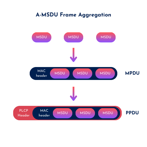
The MAC (Media Access Control) layer is responsible for handling network frames. Data is passed down from the higher layers as Service Data Units (SDUs) and wrapped with MAC layer headers to form Protocol Data Units (PDUs).
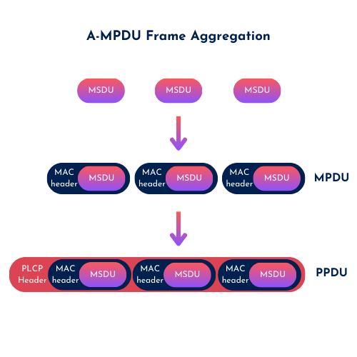
One key technique to improve efficiency is frame aggregation, where multiple frames are combined into a single transmission.
- A-MSDU (Aggregated MSDU) combines multiple MSDUs (data units from higher layers) into a single MPDU for transmission, reducing overhead by sending them as one frame. However, all MSDUs within the A-MSDU must go to the same destination.
- A-MPDU (Aggregated MPDU) combines multiple MPDUs (MAC Protocol Data Units) into a single transmission to reduce overhead and improve throughput. Each MPDU maintains its own sequence number and can be individually acknowledged, enhancing reliability. This aggregation is particularly beneficial in high-bandwidth scenarios, maximizing the efficiency of wireless communication.
802.11ax Innovations
The latest Wi-Fi standard, 802.11ax, brings several innovations aimed at improving efficiency and reducing congestion, particularly in high-density environments.
- OFDMA (Orthogonal Frequency-Division Multiple Access) allows multiple users to transmit simultaneously, dividing channels into smaller sub-channels or Resource Units (RUs) for better efficiency.
- Target Wake Time (TWT) allows devices to negotiate specific times to wake up and communicate with the access point, rather than constantly listening for transmissions. This reduces power consumption by allowing devices, especially battery-powered ones, to sleep for longer periods. TWT is particularly useful for IoT devices and applications where conserving battery life is critical.
- BSS Coloring assigns a unique identifier (color) to each network operating on the same channel to reduce co-channel interference. Devices can ignore weaker signals from differently colored networks, allowing more simultaneous transmissions on the same channel. This improves network efficiency and performance in crowded environments like offices or stadiums.
These features, along with advanced modulation (1024-QAM), make Wi-Fi 6® a game-changer for both consumer and enterprise networks.
In Wi-Fi networks, the Control Plane, Management Plane, and Data Plane each play distinct roles, working together to ensure smooth operation:
- Control Plane: This plane is responsible for network control functions, such as routing, switching, and managing the radio environment. For example, an access point (AP) adjusts its power levels, selects the best channel, or participates in roaming decisions using control protocols like CAPWAP (Control and Provisioning of Wireless Access Points).
- Management Plane: Handles the configuration, monitoring, and overall management of the network devices. This is where a network admin configures access points, monitors performance, and gathers logs. An example would be setting up SSIDs or security policies via a network controller or cloud management system.
- Data Plane: This is the plane where user data is transmitted. When a Wi-Fi client sends or receives information—like downloading a file or streaming a video—that data flows through the data plane, which facilitates the actual data transfer across the network.
These three planes work together to provide not just connectivity but also efficient, controlled, and secure Wi-Fi operations.
CWNP-defined troubleshooting methodology
To tackle wireless issues effectively, CWNP has defined a seven-step troubleshooting process:
- Define the Problem – Clearly outline what’s going wrong.
- Determine the Scale – Is it affecting a single device or multiple devices?
- Identify Probable Causes – Consider both hardware and software factors.
- Capture and Analyze Data – Take captures and use tools like protocol analyzers and spectrum analyzers.
- Observe the Problem – See what happens when the problem occurs (in your captures) – or reproduce the issue after step .
- Remediation – Apply fixes or changes based on your analysis.
- Document – Always record the problem, solution, and steps taken for future reference.
Effective troubleshooting requires methodical thinking, and mastering these steps is crucial for anyone working with Wi-Fi networks (Carpenter et al, 2021, p. 48–54).
Thank you for reading. Stay tuned for the next chapter as we dive even deeper into the world of wireless networking!
Source(s):
Carpenter, T., et al. (2021). CWAP-404: Certified Wireless Analysis Professional Study Guide (2nd ed.). Durham NC, USA: Certitrek Publishing
Disclaimer: IEEE amendment 802.11be (Wi-Fi 7®) will not be tested on the CWAP-404 exam. Any information included about this is for reference, as this amendment is not yet ratified.
Very nice summary, Robin! Good luck on your Wi-Fi journey, and enjoy!