In order to truly understand 802.11 communications, we need to look at both Layer 1 and Layer 2 information. This chapter focuses on Layer 1 to help build a solid understanding of PHY operations.
PHY Layer functions
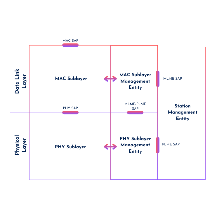
The PHY layer has many functions like modulation, demodulation, encoding, transmission, reception, carrier sensing, and clear channel assessment. These functions can be controlled by ‘services’ operating through a Service Access Point (SAP). An SAP is a kind of logical interface between two different (sub-)layers. The SAP between the MAC and PHY sublayer is called the PHY SAP.
These services are manipulated by a set of instructions called service primitives. Although these primitives are not visible in packet captures and therefore, you don’t need to know them in depth for the CWAP exam, you should know they exist and understand how the communication between Layer 1 and Layer 2 is operated. In pure essence, it’s the MAC layer signalling to the PHY layer that it wants to send a frame, and the PHY layer responds by communicating whether the medium is busy or idle.
Carrier Sensing and Clear Channel Assessment
CS/CCA stands for Carrier Sense/Clear Channel Assessment, where carrier sensing is actually sensing/detecting the carrier/RF signals and CCA is determining if the channel is available. This happens at Layer 1, while CSMA/CA (Carrier Sense Multiple Access/Collision Avoidance) operates at Layer 2. Due to the collision avoidance nature, random backoff timers are used to transmit the frames, and transmissions need to be acknowledged to confirm they are successful. Both CS/CCA and CSMA/CA are part of the contention process, which will be covered in more detail in later chapters.
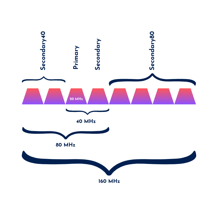
When performing CCA, the device must know which channel it is on. As we all know (you should if you’ve made it up to this website), channels can be bonded from 20 MHz to 40, 80, and 160 MHz (Wi-Fi 7 even introduces 320 MHz wide channels). Some parts of the bonded channels can be free while others are busy. When the CCA state indicates it’s busy, channel-list elements are specified to determine which parts of the channel are busy. If only one channel (20 MHz) is used, this element is absent in the primitive parameter. The different channel-list elements are named primary, secondary, secondary40, and secondary80, as seen in the illustration below.
PHY Frame Formats (PPDU)
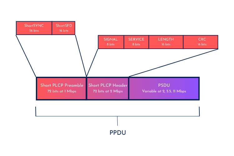
Now let’s talk a bit more about PHY frame formats (PPDU). Different PHYs have different PPDU structures. Let’s start with the beginning: a DSSS PPDU frame. We can identify the Preamble, Header, and the MPDU (= PSDU). The Preamble consists of a sync field and a Start Frame Delimiter (SFD). The sync field is a continuous stream of 1’s and 0’s, so it doesn’t matter if a device does not pick up the first couple of bits, as long as it syncs before the SFD, which will indicate when the frame will start.
Preambles are used to synchronize the transmission with the receiver, while the header indicates settings like data rates, modulation, and duration/length. These preambles, along with the header, are sent at the lowest mandatory data rate, allowing legacy devices to detect the transmission and wait their turn in the contention process. The data payload (PSDU) is sent at a higher data rate, which will be signaled within the PHY header.
Orthogonal Frequency Division Multiplexing (OFDM)
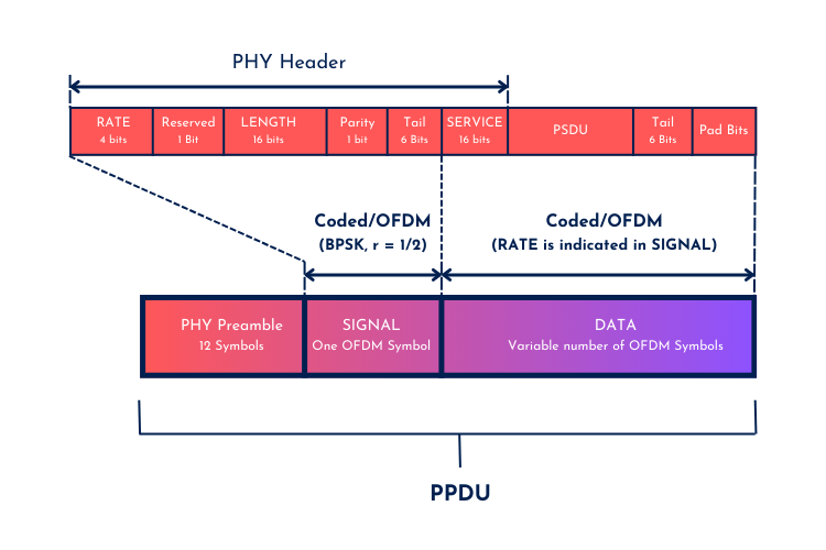
OFDM was introduced with the next amendment – 802.11a (or OFDM PHY). With OFDM, channel width went from 22 MHz to 20 MHz (as we are used to today), and each channel is divided into 64 subcarriers, of which 52 are used, and the remaining 12 are guard carriers at each end of the channel. Out of the 52 useable subcarriers, 48 contain data and the other 4 are pilot subcarriers. This PHY also paved the way for QAM modulation. An OFDM subcarrier is 312.5 KHz wide (20000 KHz / 64).
An OFDM frame looks a little different from the (HR/)DSSS frames, as the service bits (which are still considered header information) are transferred at the same rate as the data payload. Because the OFDM PHY was the first to operate in the 5GHz band, there was no need for backward compatibility.
Extended Rate PHY (ERP)
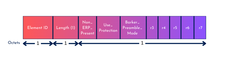
Regarding the ERP PHY, and every other PHY that follows in the same spectrum, backward compatibility is a must. ERP can use 2 frame formats: ERP-DSSS and ERP-OFDM. ERP-DSSS is quite similar to HR/DSSS, whilst ERP-OFDM uses the OFDM frame format. One might wonder how they can coexist, as the older PHY cannot read OFDM frames. The answer to this is protection mode – RTS/CTS or CTS-to-self. The older PHYs are able to hear these frames, as all management frames (like RTS/CTS) are transmitted at the lowest mandatory data rate, which the legacy devices can understand and reset their wait timer (NAV value). ERP management frames include an ERP Information Element, which indicates if there are non-ERP (legacy) devices present on the network. If this is the case, protection should be used. If it’s not the case, protection is not necessary and will improve airtime (as no RTS/CTS management frames have to be transmitted).
High Throughput PHY (HT)
HT builds further upon OFDM but has several improvements. Some noticeable examples are:
- Frame aggregation and block-ack
- Short guard interval (Optional – 0.4 µs instead of 0.8 µs)
- Channel bonding (40 MHz)
- Full use of 64 OFDM subcarriers (312.5 kHz wide) per channel, compared to 52 in 802.11a
- Multiple Input Multiple Output (MIMO)
All these newer technologies lead to an increased data rate of up to 600 Mbps compared to the 54 Mbps with OFDM. These newer features also result in a more complex preamble structure. Similar to ERP, we have an HT Information Element to indicate whether non-HT stations are present. We have three compatibility modes: legacy mode (only legacy devices present), mixed mode (both legacy and HT), and greenfield mode (only HT). The HT PHY preamble comprises different training fields and signal fields based on the operation mode.
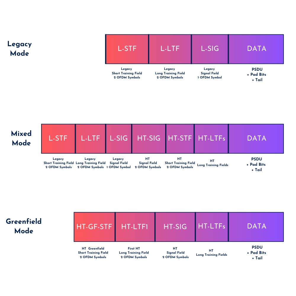
The legacy mode uses the legacy OFDM format and duplicates the 20 MHz legacy packet format into two 20 MHz halves when a 40 MHz wide channel is used (Carpenter et al, p180). In mixed mode, the preamble size is bigger because it uses the legacy OFDM preambles and appends the HT preamble fields to it. This allows for fair contention with legacy clients, as these clients can read the legacy preamble information. In a greenfield environment, where no legacy clients are present, the greenfield format will be used. The HT preamble includes multiple HT-LFTs instead of only one LTF to support multiple spatial streams and MIMO. As you can see, mixed mode is almost an exact combination of the legacy and greenfield preamble format.
HT also introduced a new type of control frame called a Control Wrapper. It’s used to carry other control frames with HT control frames. This allows a HT device to transmit “legacy” control frames in an HT format to take advantage of HT capabilities like Transmit Beamforming (TxBF). (Carpenter et al, p183)
HT Protection Modes
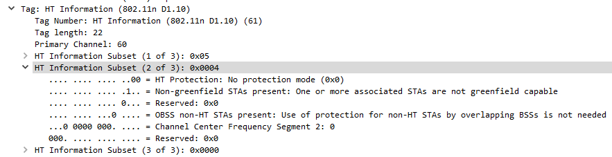
802.11n (HT) uses 4 protection modes. Looking for this mode in your capture files will give you a great idea of the environment and why legacy rates are possibly in use.
Mode 0: No protection mode – If all stations in the BSS are 20/40 MHz HT capable, or if the BSS is 20/40 MHz capable, or if all stations in the BSS are 20 MHz HT stations in a 20 MHz BSS (Greenfield).
Mode 1: Non-member protection mode – used if there are non-HT stations or APs using the primary or secondary channels
Mode 2: 20 MHz protection mode – if only HT stations are associated in the BSS and at least one 20 MHz HT station is associated.
Mode 3: non-HT Mixed-mode – used if one or more non-HT stations are associated in the BSS. (Carpenter et al, p184)
When protection is enabled (modes 1,2,3), we are mainly talking about RTS/CTS or CTS-to-self Control frames. Other options like L-SIG TxOP Protection exist in Mixed Mode, but are not explored further in this chapter.
Very High Throughput PHY (VHT)
VHT is the evolution of HT. They have a lot in common but of course, some major enhancements were introduced. Channel widths of up to 160 MHz, up to 8 spatial streams, 256-QAM modulation, and Mult-User MIMO are the most important ones to remember.
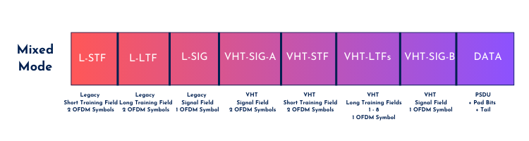
Backwards compatibility is very much needed and in reality greenfield mode is difficult to achieve in Wi-Fi, so generally speaking VHT only uses one PPDU format: Mixed mode. Two differences with HT Mixed mode are the use of extra VHF-LTF’s due to the support of more spatial streams and a second SIG field. The formation of the SIG-A and SIG-B fields are dependent on the use SU-MIMO or MU-MIMO.
High Efficiency PHY (HE)
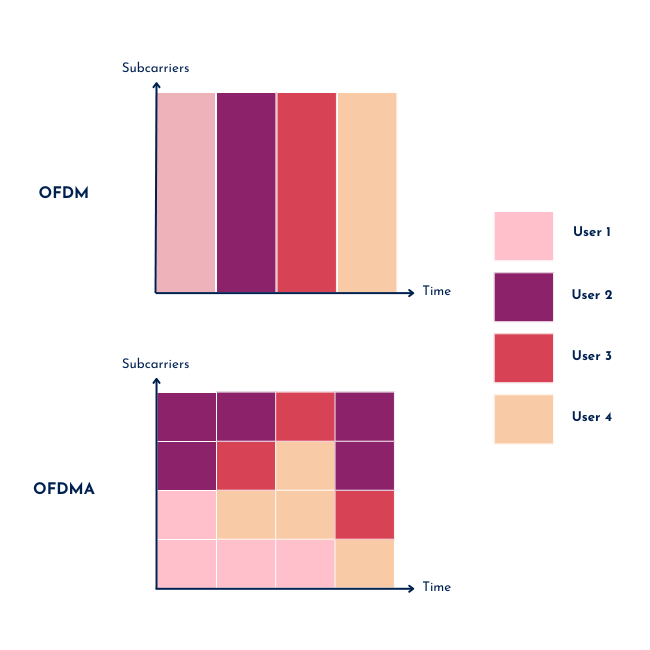
802.11ax (HE) is the first PHY to operate in the 6GHz band and introduces Orthogonal Frequency Division Multiple Access (OFDMA). Whereas traditional OFDM PHYs use all subcarriers (entire bandwidth) for the same device simultaneously, OFDMA allows to assign Resource Units (RUs) – a group of OFDM subcarriers – to specific devices (partial bandwidth). In contrast to MU-MIMO, where essentially the number of spatial streams/antennas can be split over multiple users, in OFDMA, one channel is divided into smaller frequency RUs which allows for multiple devices to transmit and receive at the same time in the same spatial stream. HE is like its name implies highly efficient and OFDMA is the “real” MU-MIMO.
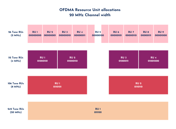
OFDMA has smaller subcarriers than OFDM, with a total of 256 subcarriers of which 242 are used for data and the others are for guarding/spacing. Subcarriers, from here on called tones, are grouped in defined sizes. Each tone has a width of 78.125 kHz – 4x smaller compared to OFDM. For a 20 MHz channel, the following tone arrangements are possible: 26-tone RU, 52-tone RU, 106-tone, and 242-tone RU. For a 40 MHz or larger channel, you can combine the 242-tone RU’s in a bigger RU depending on the channel width. The largest amount of devices that can simultaneously transmit on a 20 MHz are 9 devices using 26-tone RU’s. Logically, a smaller RU has a smaller bandwidth, which is why we’re usually not seeing 9x 26-tone RUs in production but rather a combination of the existing arrangements.
For backward compatibility reasons and because 802.11ax operates on 2.4 GHz, 5GHz and 6 GHz bands, HE has multiple possible PHY frame formats. To simplify things, for both me and you, take an non-HT (OFDM) , HT or VHT frame and append a HE preamble to it. This way, it can talk to different legacy devices whilst still transmitting its HE capabilities that other HE devices can take advantage of.
HE has a symbol duration of 12.8 µs (excl. Guard Interval) which is 4x longer than previous standards (3.2 µs). This improves efficiency in dense environments and enhances resilience against interference, especially over longer distance. Although the symbol time is 4x longer, HE’s throughput may exceed previous standards due to all the other good things HE brings to the table. HE introduced 1024-QAM modulation (MCS 10 & 11), OFDMA, BSS-coloring, Target Wake Time (TWT) and more. All these enhancements make the Wi-Fi more efficient, making it perform better and achieve a higher throughput.
Pseudo-headers
To end this chapter review, let’s talk about pseudo headers. A pseudo-header is an additional header added by the capture device (e.g., a Wi-Fi adapter in monitor mode or specialized sniffing hardware) to provide extra information about a captured frame that isn’t part of the actual 802.11 frame being transmitted over the air. These headers provide metadata that helps analyze the frame capture more effectively. This metadata includes details such as the data rate, signal strength, channel information, and other capture-related metrics that would not normally be included in the transmitted frame. The two most common types of pseudo-headers are radiotap and Per Packet Information (PPI) headers. Both are conceptually the same. Radiotap is open-source and tied to most of the open-source programmed drivers, whilst PPI headers are developed by the creators of AirPcap – so it’s only tied to AirPcap devices/drivers. Note that the radio information (channel, signal strength,..) in these pseudo-headers are derived from the capturing devices itself. It does not reveal the channel(s) other devices are transmitting on. You might want to look into management frames to see if a particular device is not transmitting on another overlapping channel.
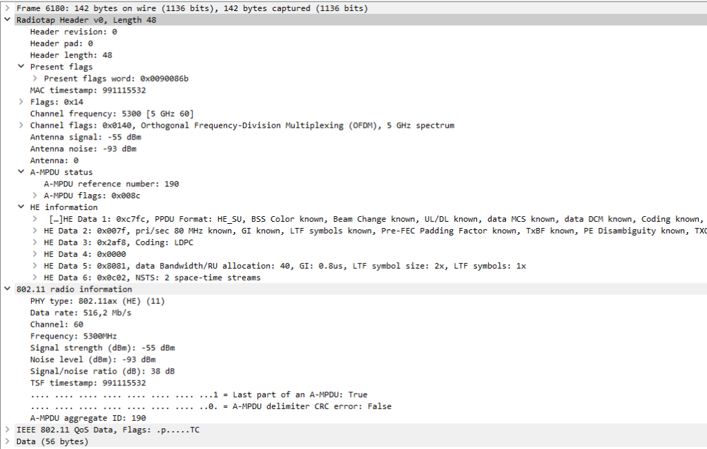
In Wireshark, you’ll notice the “802.11 Radio Information”. This section is not a header, but acts more as a readable summary from values derived from the Radiotap Header such as converting the Data MCS index to a readable Data Rate (516.2 Mbps in this case).
Now that we have a better understanding of the different PHY frame formats, the key takeaway is that backward compatibility will always be implemented in newer PHYs to support the wide range of legacy Wi-Fi clients in the real world. ERP and HT had operational modes like Greenfield and the use of protection bits. However, the more recent PHYs, like VHT and HE, operate in ‘mixed’ mode and send out legacy preambles for this purpose. As a result, the need for Greenfield capabilities has become obsolete.
Thank you for reading, I hope you enjoyed it and I hope you’ll keep following me along my journey. I appreciate your feedback on how I can improve or if I did/wrote something that’s not right.
Source(s):
Carpenter, T., et al. (2021). CWAP-404: Certified Wireless Analysis Professional Study Guide (2nd ed.). Durham NC, USA: Certitrek Publishing