The previous chapter covered Layer 1—the Physical Layer. Now, it’s time to dive into Layer 2: the Data Link Layer, or MAC Layer. This chapter will explore the different types of MAC frames, their functions, how they’re structured, and the information we can extract from them.
MAC Frame Types
There are three main types of MAC frames: Management Frames, Control Frames, and Data Frames. In the MAC header, the frame control field holds the values that specify both the type and subtype of the frame. The protocol version is always set to 00, signifying the use of 802.11. The type field determines whether the frame is a management (00), control (01), or data (10) frame, while the subtype field provides further details about the specific type of frame.
Management Frames
Management frames are responsible for establishing, maintaining, and managing connections within the wireless network. Think of them as handling the “HOW” of network operations, such as how devices join, authenticate, and interact within the network. Control frames, on the other hand, handle the “WHEN” by regulating access to the medium, coordinating timing, and ensuring efficient data flow between devices. Together, management frames set up and sustain the connection, while control frames govern the timing of data exchanges.
Management Frame Subtypes
Here are the different management frame subtypes and their purposes. Note that the bit values in the table do not indicate the order in which a Wi-Fi connection progresses. The typical connection process follows this sequence:
Probe Request → Probe Response → Authentication (A→B) → Authentication (B→A) → Association Request → Association Response
After the association response, the 4-way handshake kicks in, encrypting the wireless communication and establishing a secure connection.
| Bit Value | Description | Purpose |
|---|---|---|
| 0000 | Association Request | Request to join BSS – station (STA) informs AP of its capabilities |
| 0001 | Association Response | Reply to Assoc Req with status code (negative or positive); If positive, indicate Association ID (AID), AP returns its own capabilities and sets the EDCA parameters. |
| 0010 | Reassociation Request | Similar to Assoc Req, but initiated when STA wants to roam to other AP. Capability information is sent again, along with optional fields like 802.11r (FT). |
| 0011 | Reassociation Response | Similar to Reassoc Req. Can be positive or negative. New AID is set and updated BSS information is sent from AP to Client |
| 0100 | Probe Request | STA is requesting information from all APs on the channel. SSID can be set to wildcard (active scanning) or to a specific SSID (value derived from beacon frames – passive scanning). This frame also includes a lot of capabilities information. |
| 0101 | Probe Response | Reaction to Probe Request, sending the beacon interval and BSS Capabilities information from AP to STA. Potentially very long frame. |
| 0110 | Timing Advertisement | Primarily used with 802.11p. This Frame allows the BSS to sync a clock, for the use of bursting in transmissions, originally as a way to allow high speed vehicles to transmit when they had the opportunity. |
| 0111 | Reserved | Reserved for future use |
| 1000 | Beacon | Periodic frames sent by an AP to inform all STA on the channel of its capabilities & channel width. Potentially very long frame. |
| 1001 | ATIM (Announcement Traffic Indication Message) | Only present in an IBSS (“ad-hoc network”) – Indication to STAs in power save mode that the sender has buffered frames for them. |
| 1010 | Disassociation | Force receiving STA to reassociate (as it’s still authenticated). Includes reason codes. |
| 1011 | Authentication | STA and AP both “introducing” each other. 2 frames are sent. Once for STA > AP and once for AP > STA. |
| 1100 | Deauthentication | Force receiving STA to renegotiate entire connection. Includes reason codes. |
| 1101 | Action | Multiple actions can be sent. Most common ones are : Spectrum Management Actions – Demanding STA to perform radio/spectrum measurement tasks. E.g.: Indicating STA to scan on other channel(s), as AP will change its channel due to DFS event.QoS action frames – Changing QoS arrangements between AP and STA , informing STA of QoS value changesBlock Ack – negotiate BA parameters and instructing the STA that this feature will be used. |
| 1110 | Action No Ack | Similar to Action frames, but does not require Ack frame. |
| 1111 | Reserved | Reserved for future use |
Control Frames
According to the 802.11 standard: “MAC Control Frames are used to support the delivery of IEEE 802.11 Data, Management, and Extension Frames.”
Unlike management frames, control frames do not have a frame body with capabilities information. These frames have just some specific information elements in the header, depending on the subtype.
| Bit Value | Description | Purpose |
|---|---|---|
| 0100 | Beamforming Report Poll | AP requests STA to send beamforming feedback report. This feedback report contains Channel State Information (CSI), which is used by the AP to optimize beamforming. Beamforming is a technique that improves communication by focusing the wireless signal in the direction of the receiver, enhancing both range and throughput. |
| 0101 | VHT/HE NDP Announcement | Announcing the transmission of Null Data Packet (NDP) frame, a special type frame that doesn’t carry data but is used to measure wireless channel conditions. These measurements give APs precise channel feedback to perform beamforming. |
| 0110 | Control Frame Extension | Increases the subtype space for control frames by reusing bits 8-11, allowing for new control frame types. Often used in DMG Operations, handling grants for medium access or grant ack’s. |
| 0111 | Control Wrapper | Encapsulate other (older) control frames in HT-format, to help facilitate features like Transmit Beamforming. |
| 1000 | Block Ack Request | Request device to send a Block Ack after multiple data frames are sent |
| 1001 | Block Ack | One single ACK to confirm the reception of multiple data frames. |
| 1010 | PS-Poll | STA indicating to AP that it is awake and ready to receive buffered data (as seen in the beacon TIM). STA keeps sending this frame until More Data bit is set to 0 and can go back to sleep. |
| 1011 | Request to Send (RTS) | Protection mechanism, part of CSMA/CA. STA asking the AP when it can send its frame(s). Sets the duration field of the frame to the duration of the upcoming data transmission (+ CTS duration) |
| 1100 | Clear to Send (CTS) | Protection mechanism, part of CSMA/CA. AP granting permission to STA to send its requested frame(s). CTS without preceding RTS is known as CTS-to-self. Its duration field includes the value set during RTS minus the duration of the CTS itself. |
| 1101 | Ack | Receiver sends acknowledgment of the reception of a frame to sender. |
| 1110 | CF-End | Signals the end of a Contention-Free period in a PCF system. PCF is not used in production and usually a sign of CRC errors. |
| 1111 | CF-End + CF-Ack | Signals the end of a Contention-Free period in a PCF system and Acks the last frame. |
Data Frames
Data frames use the type value of 10 and are in general, a combination of data and an extra action, or simply data. When performing protocol analysis, we are most of the time not interested in the data payload, but simply looking for things like power-saving information or QoS information.
There are four different types of data frames that are important to know.
| Bit Value | Description | Purpose |
|---|---|---|
| 0000 | Data | Basic data frame carrying a data payload |
| 0100 | Null Data | Does not carry data – primarily used to carry the power save bit. STA uses this bit to indicate if it’s entering or exit power-save mode (sleep). This is regardless of any buffered information waiting for the power-saving STA. |
| 1000 | QoS Data | Carries data payload with QoS markings based on 802.11e Access Categories (AC) and WMM. |
| 1100 | QoS Null Data | Similar to Null Data frame, depending on STA’s support for QoS |
MAC Frame Format
Now that we’ve covered the different types of frames, let’s examine the MAC Frame format. The three MAC frame types have slightly different formats, but for the most part, we can work from a general frame format. Each frame consists of a few main components:
- MAC Header that may include Frame Control, Duration, Addresses, Optional Sequence Control, QoS Control and HT Control Fields
- A variable length Frame Body, which may contain information specific to the frame and subtype and may not be included in some frames, like RTS and CTS
- A Frame Check Sequence (FCS) which contains a 32-bit CRC (Cyclic Redundancy Check).
(Carpenter et al, p228)

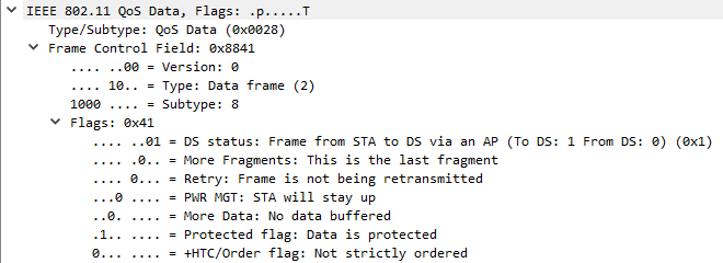
Frame Control: Used to define several parameters of the frame including type, subtype, frame direction, retries, encryption and more.
Protocol version is always set to 0. If there were to be a new version that is incompatible, this value could be incremented. For now it’s reserved for future use.
The Type/subtype fields have been covered earlier and specify which subtype of Management, Control or Data Frame this frame is.
To/From DS specifies the direction of the frame, where DS is in most cases the AP. If both To and From DS = 1, this is typically a mesh-link between two AP’s or a wlan bridge.
More Fragments is a single bit indicating if more fragments are coming (1), if this is the last frame and/or an unfragmented frame (0).
The Retry bit indicates just what you would think – if the frame is a retransmission or not. This subfield is actually very valuable as it can help you calculate the retry rate (Divide number of frames with retry bit by total number of frames sent by the STA).
The Power Management subfield or “Power Save Bit” indicates the state the transmitting device will go into after completing the transaction. 0 is remaining ‘awake’, 1 is for ‘sleeping’. In most cases, we will see this bit being transmitted as 1 in a Null Data Frame.
More Data is a way of instructing the receiver that more data is buffered and will be send, ensuring that the receiving device doesn’t go back to sleep. This is used in the direction of AP > STA (power-saving device).
The Protected Frame tells you if the frame body is protected by a cryptographic encapsulation algorithm. Management frames can be encrypted by 802.11w, Data Frames are encrypted by the encryption method used in the SSID (PSK, 802.1x, OWE,..).
+HTC/Order flag determines if an HT Control field is present after the QoS control field in the frame. This is always set to 1 in QoS Data frames or management frames in a HT, VHT or HE network when transmitting to a HT, VHT or HE station respectively.
Duration/ID: Contains either a time value or an association ID. The time value specifies the duration/time window required for the transmitter to complete its transactions AFTER the current frame. AID is used In some types of informational frames such as PS-Poll, which are not really part of a specific sequence.
Address 1,2,3, and 4: Used to communicate several potential (MAC) addresses or identifiers including BSSID, Source Address (SA), Destination Address (DA), Transmitting Station Address (TA), and Receiving Station Address (RA). Not all frames use all fields, like RTS (1-2 fields) and CTS (only 1).
ADD1 holds RA, ADD2 will hold TA, ADD 3 will hold BSSID or SA or DA, ADD4 will hold BSSID or SA.
Sequence Control: This field transmits two subfields: Fragment Number (first) and Sequence Number (second). The Fragment number is obvious whilst the Sequence Number is a 12-bit (0 – 4095) number that identifies the transaction. This number is equal across all fragments in the same transaction and thus identifies the transaction. Each time a device sends a frame, this sequence number is incremented. Not used in Control Frames.
QoS Control: Defines QoS parameters such as Traffic Category and indicates the use of A-MSDU. Only used in QoS Data frames.
HT Control: Comes in 3 variants: HT, VHT or HE. Helps define operational parameters for the MAC/PHY combination and helps signalling/calibrating the frame for Beamforming, power saving,.. In Control type Frames it can only be found in Control Wrappers. Primarily used in Management and Data Frames.
Frame Body: In Management frames, this provides mainly 802.11 information (e.g. Beacons). Action Frames specify the action in the Frame body. The body in Data Frames represent the actual upper layer data payload.
Frame Check Sequence (FCS): Contains a CRC value that is used to validate that data is received without corruption – error checking. This CRC value is a mathematical calculation that includes all fields of the mac header and frame body. When receiving a frame, this FCS value is recalculated. If the recalculation does not return the same FCS value, the frame was corrupted or damaged, and no ACK will be sent (which will lead to retransmissions).
Management Frame Formats and Information Elements
Management frames mostly follow the general frame format structure. The biggest difference and information is found in “Information Elements” included in the frame body. A beacon frame is one of the information-richest frames in Wi-Fi communications, along with probe responses.
The key components one should look for are:
- Beacon interval: Time between beacon frames. Default is 102.4 ms – approx. 10 times per second.
- Capability information: Includes if SSID is part of an ESS, if spectrum management, radio measurement, Short Preamble, Automatic Power Save Delivery and more are available, or even as simple as if encryption is used or not.
- SSID: The announced SSID (network) name.
- Supported Rates: Indicates the supported data rates, and which are basic rates vs optional rates.
- Extended supported rates: The original supported rates section was insufficient for the introduction of newer standards, thus expanding this field to allow the specification of more allowed rates.
- Traffic Indication Map (TIM): Used to indicate the AIDs of STAs with frames buffered on the AP during power save.
- Country: Indicates the operating Country and therefore the regulatory domain under which it must function.
- Robust Security Network: Indicates the security suites used for both unicast and multicast/broadcast (group).
- HT Capabilities & HT Operations: Shows the HT features and capabilities supported by the AP.
- VHT Capabilities & VHT Operations: Shows the VHT features and capabilities supported by the AP.
- HE Capabilities & HE Operations: Shows the HE features and capabilities supported by the AP.
- Vendor Specific (WME): Wireless Multimedia Extensions, which are commonly present to indicate the WMM values in use, such as the AIFSN and ECWmin and ECWmax for each Access Category (AC).
(Carpenter et al, p241-242)
Probe Request and Response
Probe requests are the beginning of the association process and is used for ‘active scanning’. A wireless station send a probe request with a destination broadcast address (FF:…:FF) on a particular channel, and wait for a response in a given time window. If no response was received, it moves on to the next channel. It can specify the SSID name it’s seeking, or use a wildcard address so that all SSID’s should respond. In most cases, we see a wildcard probe request followed by a specific SSID probe request (after receiving a probe response on the wildcard request indicating that SSID exists.). In Probe request/responses, many information elements are the same as beacon frames, where both STA and AP are announcing their capabilities. However, there are some minor things to keep in mind:
- A probe request does not contain a TIM or QoS capability frame.
- It is mainly addressed to a specific station (e.g. wildcard probe requests) unlike beacon broadcasts.
- Responses are partially tailored to the elements specified in the request
- Responses do include the beacon interval for the BSS
(Carpenter et al, p245-246)
Authentication and Deauthentication
After a Probe Request/Response transaction, an authentication frame exchange takes place, with one Authentication frame sent from the client (STA) to the AP, and another from the AP to the STA. While the frames aren’t labelled as ‘request’ and ‘response’, they follow that sequence, with the AP’s frame confirming or denying authentication. The client’s initial authentication frame includes a status code of 0, indicating a request to authenticate, while the AP’s response frame uses the status code to confirm or reject the authentication. This exchange enables the AP to validate the client before further connection steps.
A Deauthentication frame is one of the shortest types of frames, consisting of just the reason code and optional elements. A large amount of 802.11 Deauth reason codes are documented in the 802.11-2020 standard, and have been published on many (support) websites. This frame is a very crucial element in troubleshooting, as it actually tells you why a client is disconnecting from the BSS.
Association and Reassociation Request and Response
Following up on the authentication exchange, the association process kicks in, with an association request and response. The request frame tells you a lot about the client STA’s capabilities, including supported data rates and QoS information. Think of it like a client making an offer to the AP. The AP then responds with the BSS settings the client has to comply to. The response will also include a status code (accept or deny) and the Association ID (AID) that the client station has to use to identify its wireless connection.
In addition to the association request and response, there is a similar type called reassociation request and response. This type of frame can be seen in two types of events: when a connection was dropped shortly (e.g. coverage hole, elevator,..) or during a roam (moving from AP 1 to AP 2). In the first case, the reassociation frame is very similar to the association frame. During a roaming event, the information is a bit different, as both the current association information (settings, connected AP, AID,..) has to be communicated along with the regular association request information to the AP. Remember from Chapter 2 that you’ll have to capture on multiple channels to capture the full roaming event.
Control Frames
As specified earlier, Control Frames do not carry a frame body, but all the information you need is included in the header. The first header element is the Frame Control Field, which is identical to this type of field in Management and Data Frames. It is the same across all control frames.
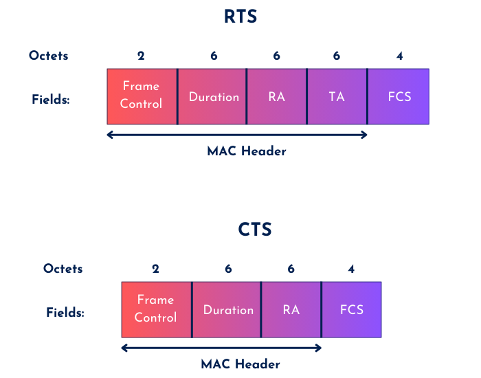
The first control frames I want to discuss briefly are the RTS and CTS Frames. The format of these are quite simple with the most important field being the duration field. If you’ve come this far, you should know that RTS and CTS are used as a protection mechanism, allowing legacy devices pick up these frames, transmitted at the lowest capable data rate, set their NAV timers and back off the wireless medium. Here are the formulas on how these duration timers are calculated:
RTS: Management or Data frame duration + CTS duration + one ACK duration + three SIFS
CTS: Value of duration field from preceding RTS field – CTS Duration – one SIFS
CTS-to-self: Management or Data frame duration + two SIFS + one ACK duration
These formulas assume all frames require an ACK. If an ACK is not required (e.g. ‘Action No ACK’ frame), simply leave out the ACK duration from the formula. The other header elements are either Receiver Address, Transmitter Address or both.
(Carpenter et al.,p251-253)
An ACK frame is sent immediately upon reception of a management or data frame to inform the transmitter that the frame was well received. Without an ACK, the transmitter assumes the frame was lost or corrupted due to interference, and retransmits the frame. The format of an ACK frame is identical to a CTS frame. Though, unlike CTS, the duration field can be zero if the more fragments bit was not set (and thus indicating that the transaction has ended). If more fragments are coming, the ACK duration value is based on the previous frame (who includes the duration value to complete the whole transaction).
Duration value of previous frame + ACK time + one SIFS
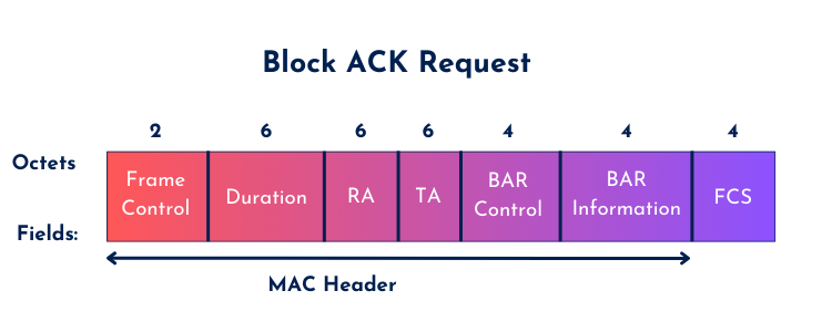
The last one I want to mention is the Block Ack Request (BAR) frame. Just like other Control frames, this is very simple. It has the structure of an RTS Frame with a BAR Control and BAR Information field.
Understanding MAC frames is fundamental to working with Wi-Fi networks. Management frames establish connections, Control frames coordinate medium access, and Data frames carry the payload – each playing a vital role in wireless communications. This knowledge of frame structures and their interactions is essential for diagnosing network issues, optimizing performance, and ensuring reliable connectivity. From daily troubleshooting to network architecture, these fundamentals shape how we manage and optimize Wi-Fi networks.
Thank you for taking the time to read this post! Your feedback means a lot to me – whether it’s suggestions for improvement or catching technical details that need clarification. I hope you found this information valuable and I look forward to sharing more insights about wireless networking with you.
Source(s):
Carpenter, T., et al. (2021). CWAP-404: Certified Wireless Analysis Professional Study Guide (2nd ed.). Durham NC, USA: Certitrek Publishing