Another important thing to understand is how one can access the medium and content for it. QoS parameters play a vital role in this as it can give priority access. We will discover how this all works, how we can make adjustments and mitigate issues.
Collision Management
Where Ethernet networks (IEEE 802.3) use a form of collision management called collision detection (CD), Wireless networks (IEEE 802.11) use a different form called Collision Avoidance (CA). The two methods that are in use are DCF and EDCA, where EDCA is DCF on steroids. All 802.11 devices support DCF and the QoS devices also support EDCA. These devices never know when a collision has happened, but when they don’t receive an ACK, they will simply retransmit and set the retry bit to 1.
DCF (Distributed Coordination Function)
DCF is the CSMA/CA method used in 802.11 networks when EDCA is not in use. The essence of CSMA/CA is that a collision can happen at any time and likely cannot be detected by the transmitter. Therefore, listening for collisions while transmitting is worthless, as the transmission can’t be aborted early.
The “Carrier Sense” in CSMA means that the devices attempt to determine whether the physical medium is available before communicating. Multiple Access means that more than one device is accessing the medium. The Collision avoidance works by one device saying that it’s going to talk for X amount of time (duration parameter), so that other devices should back off. It’s not perfect with the hidden node problem, although RTS/CTS helps mitigating that issue.
Carrier Sensing Methods
Actually, there are two main methods of carrier sensing: virtual carrier sensing and physical carrier sensing. Virtual relates to the MAC layer where the station uses a NAV timer. Think of it as a backoff timer, which can be updated when it sees a frame in the air (on the same channel) and reads the duration value. It only adds the duration value so it doesn’t completely reset its NAV timer, otherwise it might be very difficult to transmit a frame at all. When the NAV timer reaches 0, it may contend for the medium.
When MAC layer thinks the medium is free, it will instruct the PHY layer through primitives like PHY-CCARESET.request to check if the medium is actually idle. Physical Carrier Sensing works by Energy Detection (ED). How the physics work goes beyond me, but the name is clear enough I believe. If the medium is idle, it will report it back to the MAC layer and the transmission can start.
Interframe Spacing and Timing
When the channel is declared idle, the station must still wait a certain time interval between frames to make sure frames do not overlap and collide. This is called an Interframe Space (IFS). Different types of frames use different types of IFS, and within data frames, you have a difference between regular data and QoS Data frames. With QoS Data frames, this waiting period is influenced by backoff timers based on priority. I’ll cover them later on. The shorter the IFS is, the quicker a frame has access to the medium.
The different IFS with their timers are:
- SIFS = aSIFSTime (defined for each PHY)
- RIFS = 2 µs (only in HT)
- PIFS = SIFS + slot time
- DIFS = SIFS + 2x slot time
- AIFS = AIFSN(Access_Category) x slot time + SIFS
- EIFS = SIFS + AckTxTime + DIFS (AckTxTime = time in microseconds required to transmit an Ack at the lowest mandatory rate)
(Carpenter et al.,p330)
Short Interframe Space (SIFS)
SIFS is the shortest available IFS parameter in 802.11 devices preceding 802.11n (HT). It is used in following cases:
- ACK frames
- CTS frames as a response to RTS frames
- Data frames that immediately follow CTS frames
- All fragments that are part of a fragment burst, with exception of the first fragment
- All frames in PCF mode (which is not implemented anymore), with exception of the first exchange and error conditions (Carpenter et al.,p331)
The SIFS times are not that difficult to remember as there are just two values: 10 µs in 2.4GHz and 16 µs in 5 or 6 GHz. The accuracy level of this time window is allowed to be +/- 10% of the slot time for the PHY in use.
Reduced Interframe Space (RIFS)
The RIFS is a very uncommon, yet not impossible one to witness. It is only used in 802.11n (HT) greenfield networks. Legacy devices don’t support it, and with later PHY’s, other improvements were made to address efficiency and throughput. RIFS is actually the shortest IFS with just only 2 µs and used for ACK frames and data fragments. It is expected that RIFS, just like PCF, will be removed from the standard, because it became obsolete since 802.11ac (VHT).
Priority Interframe Space (PIFS)
PIFS actually came from Point (Coordination Function) IFS and was introduced with PCF, an alternative to DCF. However, PCF never got foot on the ground and was removed from the standard. The 802.11-2020 amendment re-introduced PIFS as it’s used for sounding NDP (Null Data Packet) in Transmit Beamforming and for Channel Switch Announcement frames or TIM frames. This is a longer IFS than SIFS, but shorter than DIFS or EIFS, making it still a meaningful IFS giving priority to the frame types that use it.
I’ve referenced it before and here it comes into play given the formula: slot time. The slot time is a time unit that is used in calculations such as IFS but also backoff timers. As with the SIFS time, the slot time is also not that different for each PHY. In general, the slot time for 2.4 GHz is 20 µs when using long preambles. For 2.4 GHz PHY’s with short preamble and 5/6 GHz PHY’s, the slot time is 9 µs.
Distributed Interframe Space (DIFS)
DIFS is the longest type of IFS covered so far, and is used by standard data frames. It uses the formula of SIFS + 2x Slot time. Because it is longer than SIFS and PIFS, those frames will be sent before data frames. This is the desired behavior, as for Wi-Fi to work well, a lot of the management and control frames need to be sent, to support the successful transmission of data frames. If signaling and ACK does not work properly, you would get a ton of retries and increasing the channel utilization.
Extended Interframe Space (EIFS)
An uncommon Interframe Space is EIFS, because it’s only used when a station is receiving frames, but the data transmission was incomplete or corrupted based on the FCS. This long wait time allows the station to recover from the corrupted data it received, before transmitting itself.
Arbitration Interframe Space (AIFS)
The AIFS is used in QoS devices (implementing EDCA) for the transmission of all (QoS) data frames, management frames and select control frames. The control frames that use AIFS are:
- PS-POLL
- RTS
- CTS (when not responding to an RTS)
- BlockAckReq
- BlockAck
Based on the Access Category (VO, VI, BE or BK), a different AIFS Number is specified, with the highest priority category (Voice) having the lowest value. In the formula of AIFSN(AC) x slot time + SIFS. If you compare this time to regular data frames, the higher priority categories have a shorter IFS time than DIFS, but low priority packets (BK) can actually have a longer total IFS time.
Contention Window
After the IFS delay interval has passed, stations must initiate a random backoff algorithm to obtain a random integer, which is then multiplied by the slot time. The range of these random integers (and thus the range of the random waiting time) is what we call the Contention Window, or think of it like “contention range”.
If you combine the carrier sense (CCA), followed by the IFS and the CW, you have a good understanding of the mechanisms used in the DCF Medium Access Method.
If with all these mechanisms, collisions can occur. That’s the whole reason why ACK frames exist, to increase reliability.
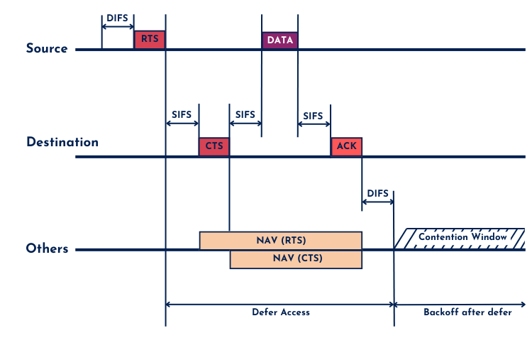
In below image, you can see a basic DCF operation according to the 802.11 standard.
Enhanced Distributed Channel Access (EDCA)
With 802.11e, QoS was introduced in 802.11 and DCF received an upgrade in the form of EDCA. Traditional QoS markings use 802.1p or DSCP to divide traffic into max eight queues on 802.3 ethernet networks. The QoS mechanism in Wi-Fi networks can assign four different queues or Access Categories (AC). These are:
- AC_BK = background = lowest priority
- AC_BE = Best Effort = low priority
- AC_VI = Video = medium priority
- AC_VO = Voice = highest priority
Based on these AC’s, a different contention window is used. The higher the priority, the smaller the contention window. As stated in the AIFS section, even different AIFS Numbers are assigned to these AC’s. All this combined; EDCA manipulates both the AIFSN and the contention window values for these four Access Categories. How the traffic gets assigned to such category, is based upon the QoS marking by the station or the traffic received on the wired port of the AP.
Wi-Fi Multimedia (WMM)
Wi-Fi Multimedia (WMM) is the Wi-Fi Alliance certification that indicates that a device implements a subset of EDCA. In addition to the AC’s, WMM also introduced WMM-PowerSave and WMM-Admission Control. WMM-PS ensures that buffered frames waiting for the sleeping station are processed from highest priority to lowest priority when the station wakes up. WMM-AC may or may not allow devices to send at the highest priority if the network is congested. If everything is sent at the highest priority, nothing really has priority. Stations have to request access to send traffic on a high priority AC, so the AP can accept or deny it based on network conditions.
Default EDCA Parameters
WMM also specifies the default EDCA parameters to use. These can be reconfigured on your APs if needed, although in most cases the default parameters work very well. Each PHY has an aCWmin (arbitrary CW minimum) variable defined:
- DSSS – 31
- HR/DSSS – 31
- OFDM – 15
- ERP – 31 or 15 (depending on the need for backward compatibility)
- HT – 15
- VHT – 15
- HE – 15
(Carpenter et al., p339)
In modern networks, you can assume that this value is 15, but you should not forget about the legacy PHYs because of Dynamic Rate Switching or the presence of legacy and/or IoT devices. In 5 GHz this will always be 15, in 2.4GHz it can be either 31 or 15. The default values are based on this aCWmin variable, but can be edited on your APs.
Below you can find them along with the CWmin value for the 5 GHz PHYs:
| AC | CW(min) | CW(max) | AIFSN |
|---|---|---|---|
| AC_BK | aCWmin (= 15) | aCWmax (= 1023) | 7 |
| AC_BE | aCWmin (= 15) | aCWmax (= 1023) | 3 |
| AC_VI | (aCWmin + 1) / 2 – 1 (= 7) | aCWmin (= 15) | 2 |
| AC_VO | (aCWmin + 1) / 4 – 1 (= 3) | (aCWmin + 1) / 2 – 1 (= 7) | 2 |
These CWmin values are the starting upper boundary of the contention window, where for the first attempt, a station will pick an integer between 0 and CWmin. If a retry is required, it will double the CWmin value and add one on each retry until CWmax is reached where it will continue to use CWmax for further retries. (Carpenter et al., p340)
WMM Implementation
The WMM parameter set can be viewed in Beacon, Probe Response and association Response frames. These are the types of frames where the AP shows off its capabilities and what should be used when implementing QoS. If a device is WMM certified, it should follow these rules.
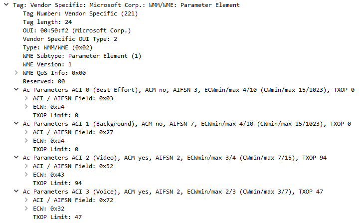
As you can notice, there is also a differentiating field called TxOP. This is the Transmit Opportunity, and it defines the maximum amount of time the STA may use the medium in bursts. A TxOP of 0 means the STA can send only one frame after which it has to start the contention procedures again.
Remember that WMM is only “Wi-Fi QoS” and for e.g. VoIP to work properly, end-to-end QoS should be implemented. This includes all systems from Wi-Fi Phone to AP to Switch(es), routers, telephony gateways. Voice is very sensitive to latency and jitter and a delay is immediately noticeable, so that’s why it should have a higher priority over regular data traffic where a larger delay of X milliseconds can go unnoticed.
It is important to understand how wireless networks handle access to the medium in order to know when W-Fi is not working as expected. We covered everything from “basic” DCF to EDCA with QoS, showing how these mechanisms ensure wireless devices can communicate effectively while minimizing collisions. The IFS timings and Contention Windows we discussed are vital in prioritizing different types of traffic – making it possible to have your VoIP call working properly while other traffic flows through the network.
Thanks for making it up to the end! If you have any questions about the topics covered, feel free to reach out through the comments below or on LinkedIn.
Source(s):
Carpenter, T., et al. (2021). CWAP-404: Certified Wireless Analysis Professional Study Guide (2nd ed.). Durham NC, USA: Certitrek Publishing