In this blog post, we dive deep into Chapter 8 of CWAP-404, which focuses on MIMO (Multiple Input, Multiple Output) and advanced wireless technologies, including transmit beamforming (TxBF), spatial multiplexing, and the innovations brought by 802.11ax (HE). We’ll also touch on how uplink and downlink OFDMA operate, the role of trigger frames, and the importance of understanding device capabilities for optimized network performance.
MIMO and Multipath
MIMO (Multiple Input, Multiple Output) leverages multiple transmit and receive antennas along with spatial streams to provide spatial degrees of freedom. These degrees can be used for antenna diversity, spatial multiplexing, or a combination of both to enhance wireless communication.
Multipath, a phenomenon where signals arrive at the receiver through multiple paths due to reflections, is often a challenge for SISO (Single Input, Single Output) systems. In SISO, if a signal copy arrives out of phase, it can cancel or corrupt the frame. Antenna diversity in SISO helps mitigate this but doesn’t fully resolve the issue. To illustrate, think of your ears as a 2×1 SISO system: if one ear hears better, you rely on it more. Similarly, in SISO, the ACK is sent using the same antenna that received the strongest signal.
MIMO systems excel by processing “out-of-phase” signals received across multiple antennas, distinguishing them for improved throughput and reliability. However, MIMO isn’t invulnerable—if multiple signals arrive at the same time and cancel each other, a phenomenon called nulling occurs, similar to issues seen in SISO.
Spatial Multiplexing
Spatial multiplexing is a key feature of MIMO that transmits multiple, independent bit streams simultaneously from different antennas, increasing throughput linearly with the number of spatial streams. For example, while stations are often configured as 1×1:1 or 2×2:2, modern APs range from 2×2:2 to 8×8:8 configurations, with 2×2:2 and 4×4:4 being the most common.
Picture spatial streams as lanes on a highway. In traditional MIMO, only one station can “drive” in the lanes at any given time. MU-MIMO (Multi-User MIMO), however, allows multiple stations to utilize these lanes simultaneously. For instance, a 4×4:4 AP can accommodate four 1×1:1 stations transmitting in parallel or a combination like two 1×1:1 and one 2×2:2 station.
Despite having fewer antennas, stations benefit from MIMO in other ways. A 1×1:1 station communicating with a 3×3:3 AP can still enjoy MRC (Maximum Ratio Combining) gains. Reflections create additional signal copies, which the AP combines to improve signal quality.
The Wireless Channel is a matrix
The wireless channel can be visualized as a matrix, shaped by the geometry of the transmit and receive antenna arrays and the environment’s reflections. In rich scattering environments, this channel matrix can be inverted to separate signals, allowing MIMO to decode transmissions that would confuse a SISO receiver. Simply put, MIMO thrives where SISO struggles. (Carpenter et al., p376)
When implementing spatial multiplexing, ensuring that different streams don’t interfere with each other is crucial. In contrast, beamforming, where a single stream is transmitted across multiple antennas, relies on the coordination of signals so they arrive in phase at the receiver. This alignment enables MRC gains, improving the overall signal quality. Beamforming is performed at the transmitter to improve the signal strength at the receiver.
MIMO Coordination and CSI
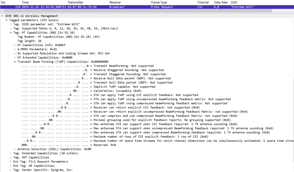
MIMO’s success depends on careful coordination. While much of this work is handled in the preambles, additional Channel State Information (CSI) may be required to refine transmissions. Devices advertise their MIMO capabilities in the HT Capabilities field, detailing which features—like spatial multiplexing or beamforming—they support.
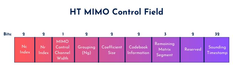
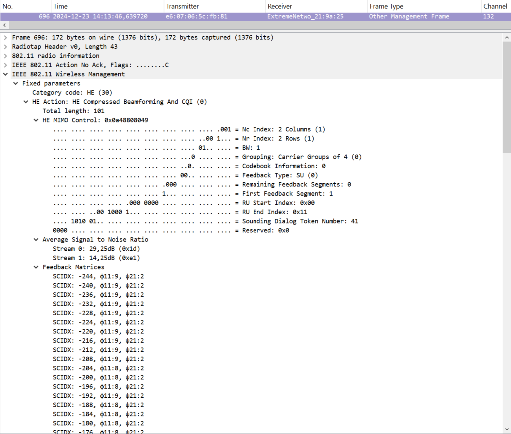
CSI can be requested using an HT Action Frame, which includes a MIMO Control Field and a CSI Report Field. The CSI Report provides the channel matrix as perceived by the receiver, feeding it back to the transmitter to adjust its beamforming and optimize the link. Below is an example of the HT MIMO Control Field for reference:
Transmit Beamforming (TxBF)
Transmit Beamforming (TxBF) uses multiple antennas to strategically transmit a signal by varying its phase, ensuring it arrives at the receiver with maximum strength. (Carpenter et al., p. 387) The result is improved signal strength at the client, leading to a higher Signal-to-Noise Ratio (SNR). This enhancement enables the use of more complex modulations, achieving higher data rates.
While TxBF benefits from action frames for refinement, it primarily relies on a calibration sequence involving Null Data Frames and HTC fields. Here’s how the process unfolds:
- Calibration Start Frame: A QoS Null Data Frame initiates the calibration process, with the TRQ bit set to 1.
- Calibration Sounding Response Frame: An Ack+HTC frame, sent by the responder, allows the initiator to estimate the MIMO channel.
- Calibration Sounding Complete Frame: A QoS Null+HTC frame with the CSI/Steering subfield of the HT Control field set to 1, enabling the responder to estimate the MIMO channel.
- Normal Ack Frame: A standard acknowledgment finalizes the calibration exchange.
Each calibration sequence has a unique identifier located in the Calibration Sequence Subfield of the HT Control field.
VHT MIMO and Enhancements
VHT (Very High Throughput) MIMO builds on HT (High Throughput) MIMO with significant enhancements, such as:
- Support for up to 8 spatial streams.
- Improved sounding protocols for more accurate beamforming.
- Introduction of MU-MIMO (Multi-User MIMO) and MU PPDUs (Physical Layer Protocol Data Units).
- Enhanced MCS data rates and VHT Link Adaptation.
VHT MU-MIMO uses Group Identifiers (GIDs) to direct specific spatial streams to individual stations. Each receiving MU-MIMO client decodes its own stream. However, this requires a high SNR to ensure the sounding and coordination processes are accurate, making it less effective in high-density environments where SNR tends to be lower.
To maximize MU-MIMO efficiency, protocols like Block Ack and frame aggregation mechanisms (A-MSDU and A-MPDU) are used.
- A-MPDU aggregates multiple MPDUs into one PPDU, improving throughput for large packets.
- A-MSDU, on the other hand, aggregates MSDUs into a single MPDU, reducing CRC overhead, making it more efficient for smaller packets.
By balancing these methods, VHT MIMO achieves greater efficiency and throughput, provided the medium access contention is carefully managed.
Beamforming feedback
Similar to HT MIMO, VHT Beamforming relies on recipient feedback for optimal performance. However, VHT Beamforming incorporates explicit feedback mechanisms, initiated by the transmitter through a VHT NDP Announcement Frame, followed by an NDP frame. The process includes:
- The beamformer lists one or more station AIDs in the VHT NDP Announcement Frame, signaling the beamformees to act.
- The first sounding NDP is targeted at one station. If multiple stations (for MU-MIMO) need to send their compressed beamforming information, subsequent Beamforming Report Poll frames are sent directly to those stations.
This feedback loop ensures the transmitter receives detailed location and angle information from the beamformees, encapsulated in VHT Compressed Beamforming Action Frames. The action frames contain a VHT Control Field and a VHT Compressed Beamforming Report Field, essential for fine-tuning the beamforming process. 802.11ax (HE) beamforming does work in a similar way, providing feedback
802.11ax (HE) and MIMO
802.11ax, also known as High Efficiency (HE), marks a significant milestone as the first PHY to utilize the 6 GHz frequency band. Alongside this advancement, it introduces a new modulation technique: Orthogonal Frequency Division Multiple Access (OFDMA). OFDMA divides the channel into smaller subchannels, known as Resource Units (RUs), enabling differentiation of users based on frequency allocation rather than antennas or spatial streams as in traditional MIMO systems.
This shift means that VHT MU-MIMO’s approach to spatial streams doesn’t apply directly to RUs in HE. When configuring your network, you’ll often face a choice between MU-MIMO, OFDMA, or disabling both and relying on regular MIMO. The general consensus is:
- OFDMA excels in environments with a high number of users who don’t require large bandwidths. It efficiently allocates smaller RUs to these users.
- MU-MIMO shines when multiple clients need to transmit simultaneously and require higher bandwidths, provided there’s good SNR—ideal for applications like video calls.
While theoretically, OFDMA and MU-MIMO can work together, the practical implementation depends heavily on client support for HE features. A single RU can, in theory, be transmitted to a different user per spatial stream, combining the strengths of both methods. However, as I’m still exploring these technologies in the field, I haven’t personally observed or deeply analyzed this interplay yet.
Downlink and Uplink OFDMA/MU-MIMO
Most discussions focus on Downlink (DL) OFDMA and MU-MIMO, where an AP transmits to multiple stations. However, 802.11ax also supports Uplink (UL) OFDMA and MU-MIMO, where multiple stations transmit simultaneously to a receiving AP.
The coordination for uplink transmissions involves Trigger Frames and Multiuser RTS (MU-RTS). A Trigger frame is a control type of frame and has the following format:
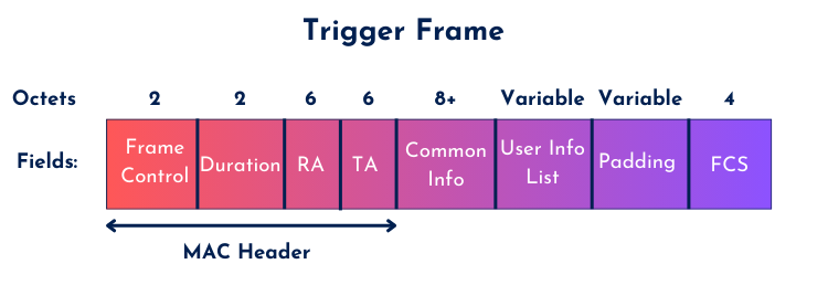
- RA: Set to broadcast address and thus destines for multiple stations.
- TA: Set to the AP transmitting the trigger frame. Can be set to the BSSID if MBSSID is in use.
- Common Info: Defines Trigger frame type (0 = Basic, 3 = MU-RTS,..) and several other parameters like AP Tx Power.
- User Info List: A list of devices that are being solicited and the RU’s that they should transmit on.
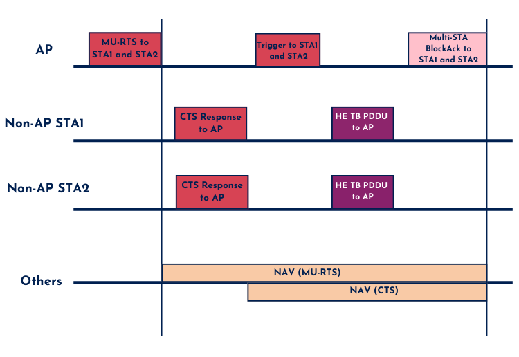
An AP will most commonly use an MU-RTS trigger frame to prepare UL-OFDMA transmissions. These can be either only CTS and ACK simultaneously, or the STA could actually send Data frames on the uplink.
Here are two possible scenarios:
- Single MU-RTS, Multiple CTS: An MU-RTS is followed by CTS responses from multiple stations, then a DL-OFDMA transmission from the AP, and finally individual Acks from the stations.
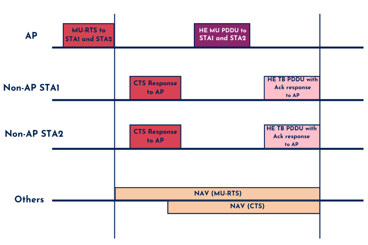
- Trigger Frame Sequence: After an MU-RTS and CTS sequence, a trigger frame prepares multiple stations for simultaneous UL transmissions. The AP then acknowledges these transmissions through DL-OFDMA.
Buffer Status, Timing, and Power Adjustments
The AP determines which stations have data to send by analyzing Buffer Status Reports. Buffer information can be supplied through the buffer queue length in the QoS control field or by using a BSR Control subfield. These Buffer Status Reports can also be polled by a BSRP-type (Buffer Status Request Poll) trigger frame
Two critical considerations for UL-OFDMA are timing and transmit power:
- Timing: The standard specifies that stations must transmit UL-OFDMA frames within a SIFS (16 μs) plus an additional 400 ns after receiving the trigger frame. RF propagation time isn’t a major issue, as a signal can travel approximately 100 meters in 334 ns, comfortably within the 416 ns limit.
- Transmit Power: Without adjustments, a nearby station’s high transmit power could overpower a weaker signal from a distant station. To mitigate this, power pre-correction is used. The trigger frame instructs stations either to transmit at maximum power or to adjust their transmit power based on this formula: Tx(STApwr) = Tx(APpwr) – Rx(pwr) + TargetRx(pwr).
Device Support for MIMO Features
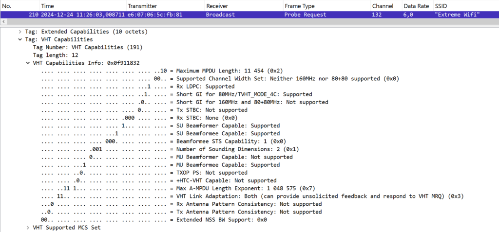
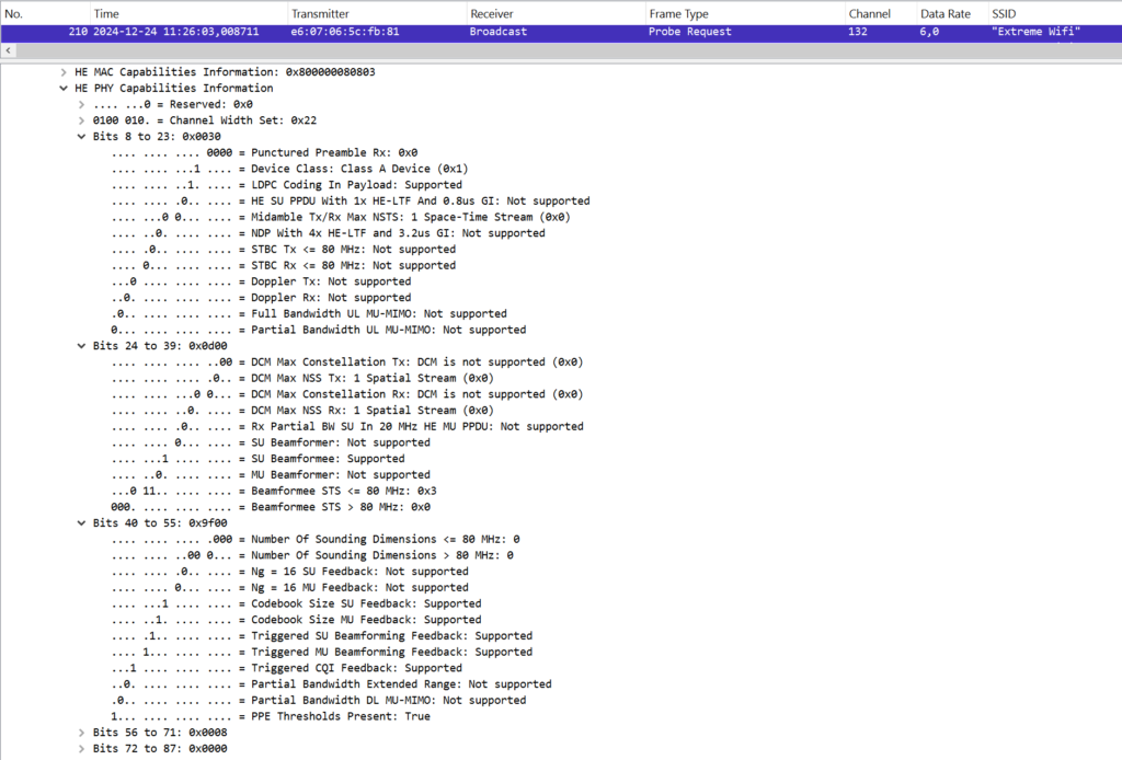
Not all devices support every MIMO capability, and the features vary between devices. For instance, my Samsung S21 phone lacks support for HT TxBF calibration, MU Beamforming as a transmitter (though it can receive MU Beamforming), UL-MIMO, and partial bandwidth DL-MIMO. However, it supports many newer methods like VHT NDP Announcement frames and HE Trigger frames. I haven’t had the time yet to look into different device types and see if this is a trend to not support these older functionalities under the hood of backward compatibility.
Each device’s capabilities significantly influence how it interacts with the network, highlighting the importance of understanding client limitations when deploying advanced features.
Thank you for exploring this chapter with me! We’ve journeyed through the intricacies of MIMO, beamforming, and the innovations in 802.11ax that are shaping the future of wireless communication. I hope this post provided clarity on these advanced technologies and inspired deeper curiosity. If you have insights or questions, feel free to share them—I’d love to hear from you.
Source(s):
Carpenter, T., et al. (2021). CWAP-404: Certified Wireless Analysis Professional Study Guide (2nd ed.). Durham NC, USA: Certitrek Publishing